
Note: This is an automated translation (using DeepL) of the original German article.
((MODYPLAN)) - Simulation for healthcare buildings
The early phases of planning
The planning of healthcare buildings is process driven: complex work processes that need to be supported determine the spatial concept - and vice versa. The system consists of two parts: spatial structures and processes.
Both parts have a high degree of formalization right from the start. This makes the system ideal to “run through” by means of simulation. So far, this is not done in practice - or only in late phases of the project - when changes to the structure and functioning of the building are very difficult to make. Figure 1 shows the planning process schematically before tendering and after tendering of a planning project.
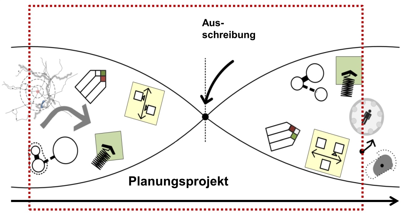
Figure 1: The Big Bang in planning. After the call for tenders, the process usually starts all over again. ((MODYPLAN)), on the other hand, allows a much earlier intervention in the planning phase.
((MODYPLAN)) takes the opposite approach: The developed simulator supports planning already in early phases, when spatial structures and work processes are in the making and want to be played out from the process point of view. Spaces, functions and processes are not static, but influence each other. They are the subject of the simulation and its task is a comparison between different variants and a support of frequent changes, as they are common in early planning. ((MODYPLAN)) thus helps to accelerate planning and to prevent expensive planning mistakes.
What can ((MODYPLAN)) do?
With ((MODYPLAN)), treatment chains are simulated and compared on various space schemas. Based on this, resource utilization is further investigated.
Simulation of treatment chains
The central core of the simulation is the treatment chain of patients. This can either be self-generated or imported from existing data sources such as Excel, SAP or other data bases (see Figure 2).
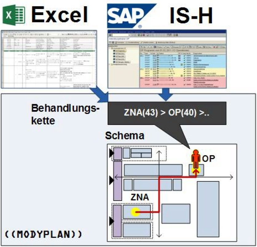
Figure 2: The treatment chain of each patient is simulated on a schematic plan.
A patient’s treatment chain represents an ordered series of functional units that the patient is expected to occupy over the course of his or her treatment, along with an indication of how long he or she is occupying them. In the simulation, the functional unit, which has a “behavior” itself, takes over the further processing of the patients, who, so to speak, make a request to the functional unit (FU). As shown in Figure 3 a), a FU can have a capacity (in this case 2), other patients have to queue. However, as shown in Figure 3 b), an FU can also consist of nested sub-units.
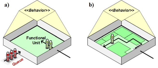
Figure 3: Representation of the behavior of a functional unit.
Resource utilization
Of central interest to the modeler is, of course, the resource utilization when simulating existing processes on the created layout/blueprint. As can be seen in Figure 4, a resource utilization can be plotted over time for each functional unit, also taking into account the space requirements of each resource.
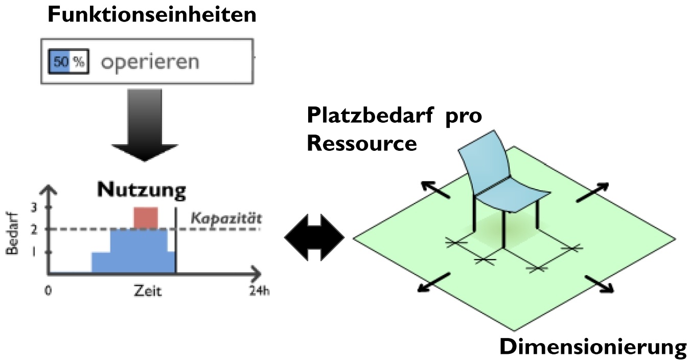
Figure 4: Resource utilization of functional units considering space requirements per resource.
Now, not only one plan can be created and tested, but also several plans and variations of them, which can subsequently be compared directly with each other.
Functionality of the ((MODYPLAN)) Simulator
The simulator itself allows three modes: editing includes the creation of the room plan itself together with the definition of which data (and subsequently treatment chains) should then be simulated on it.
Edit: Creating the models
In Edit mode, the functional units are created, along with their behavior, as shown in Figure 5.
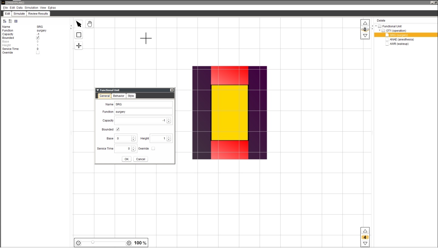
Figure 5: The edit mode in ((MODYPLAN)) allows the creation of functional units and their behavior.
Here, of course, the planning of several levels (floors in buildings) is also possible. Displaying on a finer or coarser grid is also allowed.
Simulate: Simulation of the treatment chains on the created plan
In the second mode, the simulation is visualized in 3D on the previously created plan, as shown in Figure 6. Patients work through their treatment chains.
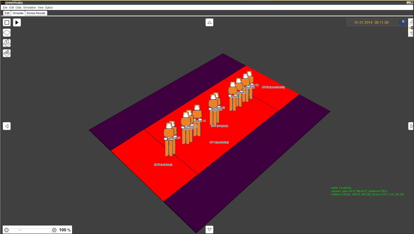
Figure 6: The simulation of the processing of treatment chains of the individual patients.
Results: Comparison of the results of different plans.
The results of the simulation can now be visualized and also compared with results of previous simulations, as can be seen in Figure 7.
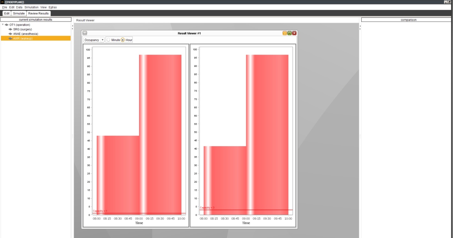
Figure 7: The results of the simulation can be visualized and compared. On the left the current resource utilization, on the right one from a previously performed simulation.
Several variants of a comparison can be selected here, such as a bar chart.
Target group
Architects and developers of health care facilities are the primary target group for the use ot he ((MODYPLAN)) tool. Operators of health care facilities are the second group which can hugely benefit of the tool’s capabilities.
Project Team - Research Units involved
- Institute of Architectural Sciences of TU Wien
Contact person: Dipl.-Ing. Dr.techn. Gabriel Wurzer - Institute of Analysis and Scientific Computing of TU Wien
Contact person: Ao.Univ.Prof. Dipl.-Ing. Dr.techn. Felix Breitenecker - ((MODYPLAN)) was funded by the Vienna Business Agency within the framework of the Call Smart Vienna 2012